


Read this article in French German Italian Portuguese Spanish
The foundation of every lift: why ground support matters

04 March 2025
Newton’s Third Law of Motion holds that for every action, there is an equal and opposite reaction. To maintain balance, when one object exerts a force on another (a crane on the ground, or your foot against the floor), the second object exerts a force against the first object that is equal in magnitude but opposite in direction. If the second object lacks adequate stability or capacity, failure results.
 To ensure adequate foundation (ground) support for heavy lift operations, three basic elements need to be clearly and thoroughly understood by the lift planner: ground stability, ground capacity and knowledge of the lift itself.
From the invention of construction cranes circa 600 BC by the Greeks, and continuing through today, there has been a basic understanding that adequate ground stability, and adequate ground capacity, are both essential in ensuring safe and efficient lift operations.
So, whether lifting a 10,000-ton topside, or one’s backside from the couch, every safe and successful load movement depends on supporting conditions being both stable and possessing adequate capacity. Hence, every lift begins “below ground” with the universal need for adequate foundational support.
Notwithstanding its centuries-long recognition, the subject of ground support recently has garnered even greater visibility within the heavy lift community. Examples of this heightened focus can be seen in SC&RA’s newly published Guide to Outrigger Pad Materials, Selection and Usage and the soon-to-be published nonmandatory appendix to ASME P30’s Standard Appendix D – Planning for LHE Foundation and Support.
Quick caveat – the content of this article focuses on recommendations for larger capacity/more complex/critical “engineered” lifts. It is understood that the economics of “taxi” crane operations limit or preclude the ability to carry out many of these recommendations. However, they can help bring into focus the need for this type of information, regardless of lift size or complexity.
Ensuring ground support
To ensure adequate foundation (ground) support for heavy lift operations, three basic elements need to be clearly and thoroughly understood by the lift planner:
Ground stability – knowledge of the integrity of the ground’s surface and its subsurface conditions, including knowledge of underground facilities (foundations, tanks, utilities, etc.), the condition of those facilities, and their three-dimensional location (coordinate position and depth of cover), areas of potentially unconsolidated soils and subsurface voids.
Ground capacity – mechanical capacity of the soils, pavement or elevated structure to resist deformation and support the imposed loads.
Knowledge of the lift itself –identification of specific lift handling equipment (LHE) to be deployed, any assist equipment to be deployed, and related ground bearing reaction forces (ground bearing pressures, a.k.a. GBPs) to be imposed on the ground.
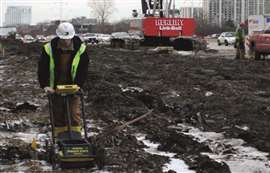 Geophysical methods collect data over wide swaths and broadly offer a depiction of subsurface conditions across the site. Analysis of this data allows for the identification of subsurface voids and areas of unconsolidated soils, with their positions and extents being estimated.
Ground stability
Gaining knowledge of the site’s surface and subsurface conditions is a critical first step in the lift planning process, with its own critical first step being the collection of available historic and project related documents. Aerial photographs (current and historic), topographic surveys, geotechnical reports, utility maps and atlases, civil drawings and site logistics plans, will all help inform the planner of facilities and underground elements that may exist. With this information in-hand, the next step is to perform a physical site survey. Site surveys offer the opportunity for validation and documentation of as-is conditions.
In planning the site survey, it is important not to ignore operating locations for assist equipment, or travel paths for load and lift related equipment egressing or traversing the site.
The survey process begins with a walkdown reconnaissance of the site to observe ground surface conditions and above ground elements. The walkdown is also used to identify other potential lift hazards such as utility structures, adjacent basements, foundations and elevated structures.
Though manual measurements of these features may be used to document them, today’s technology allows for 3D data capture. Terrestrial laser scanning, LiDAR, SLAM (simultaneous localization and mapping) and/or photogrammetry, including “drones” (unmanned aerial systems) are all viable data collection technologies. While each is subject to its own specific applicability, they offer the ability to completely and accurately capture conditions across a site.
The combination of geophysical and geotechnical testing is highly recommended for underground assessments. Taken together, they offer a comprehensive view of subsurface conditions. Various ASTM standards govern geophysical and geotechnical test methods.
Geophysical testing uses noninvasive techniques, such as ground penetrating radar (GPR) to develop a “qualitative” understanding and characterization of subsurface conditions. Geophysical methods collect data over wide swaths and broadly offer a depiction of subsurface conditions across the site. Analysis of this data allows for the identification of subsurface voids and areas of unconsolidated soils, with their positions and extents being estimated.
A further benefit of a GPR survey is its ability to discover and validate the presence of various underground facilities, including metallic and non-metallic materials. GPR grants the analytical ability to document the depth and position of underground utilities, concrete foundations and the like. Pipe and cable handheld locators can also be used in these surveys to assist in establishing the locations of conductive underground utilities.
It is important to note that there is nothing intrinsic in any geophysical data that specifically identifies, or differentiates, one subsurface target (a.k.a. “anomaly”) from another. In other words, there is nothing in GPR data that automatically identifies a particular linear target as a sewer or that automatically differentiates a sewer from a gas line from duct package from a tree root. Proper evaluation of this data requires expert analysis and additional information (i.e., historical and project related documents) to put the data in context and make it genuinely useful.
Geotechnical data collection is a physically invasive process that yields “quantitative” data for the soil material itself. A comprehensive geotech survey includes physical sampling of the soils at specific locations (soil borings). Analysis begins at the time of collection with the recording of the number of blows it takes to drive a split-spoon sampler six inches into the ground (“blow count”) and visual assessment of the sampled materials; the analysis culminates in a test laboratory.
A quick, cost-effective, alternative geotechnical method to evaluate soil strength is Dynamic Cone Penetometry (DCP). It involves driving a metal cone on a graduated rod into the ground using a standard weight dropped from a fixed height and measuring the penetration per blow to assess soil resistance. Penetration rates are correlated with the California Bearing Ratio (CBR) from which soil stiffness is calculated.
A final requisite to site data collection is the establishment of “land-survey control” and/or “geo-referencing.” The known alignments and locations of surface features and data collection points are critical for assessment of the proposed lift and proper layout of improvements and lift equipment.
Ground capacity
Once site conditions have been documented and characterized, the mechanical bearing capacity of the soil needs to be determined.
Relying on geotechnical test data, a competent person can calculate the ultimate soil bearing capacity for the given location. Ultimate bearing capacity of soil is generally defined as the maximum load per unit area that the soil can support before it fails. It is a critical factor in establishing the allowable ground bearing capacity for the proposed lift.
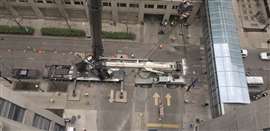
 Dearborn Companies’ work spans crane deployments on elevated structures, dense urban streets, power and industrial plants, and wind farms, as well as engineered applications of complex scaffolds, shoring and earth retention systems.
Regardless of the geotechnical test method used, the data represents a “snapshot” of the ground conditions at that very specific location. Multiple test points are needed across LHE deployment area as conditions between the points are inferred or interpolated.
Utilizing the ultimate bearing capacity and applying a “design factor” (a.k.a. “factor of safety”), the competent person then calculates the allowable ground bearing capacity for the proposed lift. A design factor is a multiplier applied in this case to the ultimate bearing capacity to account for uncertainties in material properties and unknown environmental effects, and to provide a margin of safety against catastrophic failure.
Understanding the lift
Once the existing conditions are documented and site ground capacities are known, final the planning of the lift can be undertaken. Balancing calculated LHE ground force reactions with the allowable ground bearing capacity will inform and shape decisions on the use and positioning of crane pads and mats, the potential need for and scope of ground improvements, or even potential change in the LHE selection or lift location.
No matter how meticulous the lift plan or elegant the rigging, nothing survives bad footing – every lift begins, and ends, with what’s below.

THE AUTHOR
Mike Walsh, a member of ASME P30, is president of Dearborn Companies, a third-generation family company that has provided engineering and construction consulting for over 70 years. Dearborn Companies’ work spans crane deployments on elevated structures, dense urban streets, power and industrial plants, and wind farms, as well as engineered applications of complex scaffolds, shoring and earth retention systems.
STAY CONNECTED


Receive the information you need when you need it through our world-leading magazines, newsletters and daily briefings.
CONNECT WITH THE TEAM