


Read this article in French German Italian Portuguese Spanish
Power towers 2: large luffing cranes for wind turbine work
12 December 2024
New tower crane concepts for wind turbine installation. Part two of an epic series written by ICST special correspondent and global tower crane authority Heinz-Gert Kessel
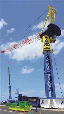
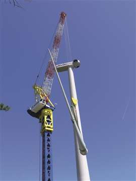 First unit of the Kitagawa JCW1800K on its second job site. Image: H-G Kessel
The second part of this report on tower crane applications for wind turbine erection projects continues with a close look at some more large luffing jib models.
Following on from part one’s look at IHI Shimizu’s unusual designs, we turn to fellow Japanese tower crane manufacturer Kitagawa Iron Works Co., Ltd. It collected field experience for its JCW1800 launched in 2020 when it was operated by TA Lift Co. This rental company for wind turbine installation tower cranes was jointly formed by Achia Co., an expert in heavy transport and rigging operations, and Toko Electrical Construction co., Ltd.
It was the first wind turbine installation tower crane designed in Japan. Up to 140 tonnes can be lifted at a 12.5 metre radius to 140 metres high in its JCW1800K version. Depending on the hook reeving, which can be changed using a remotely operated pin, the same crane can be used as a 95 tonne capacity JCW1600K.
There is also the 70 tonne capacity JCW1400K. Up to a mast height of 75 metres the tower can be just 2.5 x 2.5 metres for easy transport on standard trucks.
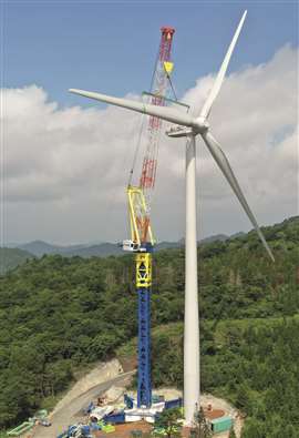 A typically cramped woodland site for the Kitagawa JCW1800K. Image: H-G Kessel
To reach a 91.4 metre free standing height, additional 3.2 x 3.2-metre-wide base tower sections are added. Note that no leg bracing is needed.
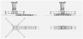
It follows the typical Japanese method of jacking the crane which allows insertion of up to two tower sections as one 15.2 metre long unit. A special cross-shaped undercarriage was also developed to speed up installation.
Moves on SPMT
To further improve the fast relocation ability for wind farms Kitagawa also developed a specialized transport system for its JCW1800K. It uses self propelled modular transporter (SPMT). In this case the complete machinery deck, with the A-frame and base jib section (to keep the luffing ropes in place) is lifted on one SPMT carrier with the help of a 550 tonne capacity wheeled mobile crane in one lift.
The climbing unit and base tower section form another SPMT load. This method allows the centre of gravity of the crane components being driven around to be very low, helping stability.
At the time of writing one JCW1800K had been produced. According to Kitagawa it turned out that strict transport restrictions in Japan meant the accepted size of wind turbine didn’t require a crane as big as the 1,800 tonne-metre class for the domestic market. TA Lift and Kitagawa, therefore, developed the smaller JCW1250 with a 95 tonne capacity at 12.5 metres radius.
 The compact machinery deck of the Kitagawa JCW1800K. Image: H-G Kessel
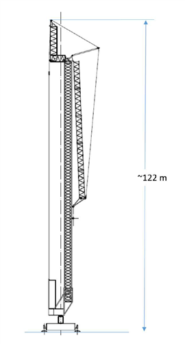
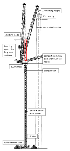
A freestanding tower height of 80.9 metres and 51 metre jib giving a 130 metre working height can be reached with a counter jib radius of just 8.7 metres.
Major benefit
Its main innovation is that it will have an hydraulically foldable 16 x 16 metre crane base section with hydraulic levelling outriggers of the type well known on large mobile cranes. This base can be transported as a 23.2 metre long and 3.85 metre wide unit.
Its method of inserting tower sections when climbing means it has a traditionally wide machinery platform. Kitagawa redesigned it, however, in such a way that by simply disconnecting the operator cabin and the access platforms, the width of that machinery deck can be reduced to 4.95 metres. A common feature of cranes in this class in Japan is an 8 to 10 metre wide machinery deck. These need a complicated and time consuming split deck design for transport.
Thanks to its compact machinery deck when rigged, the JCW1250K can be relocated more easily between turbine sites on a wind farm. Even the mast and jib sections are designed to allow transport in pairs, as 4.55 metre wide loads, on standard 3.0 metre wide SPMT modules.
 Transporting the A-frame of the Kitagawa JCW1800K on SPMT. Image: H-G Kessel
As is already the case with the JCW1800K, the smaller crane’s machinery deck, A-frame and jib base can be transported as one SPMT load with just a 4.2-metre-high centre of gravity. In contrast to the 107 tonnes of the JCW1800K, the smaller crane’s unit weighs 80 tonnes, allowing a smaller assist crane.
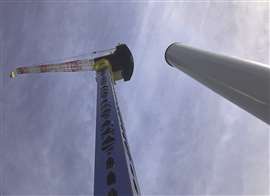
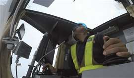 A large window in the cabin of the Kitagawa JCW1800K is to allow the best view of the load, especially when the jib is raised. Image: H-G Kessel
Unlike the JCW1800K, the size of the tower section, even for the highest free-standing capacity, is kept to 2.05 x 2.05 metres. Again, no bracings are necessary between the tower base with the cross-shaped legs which helps reduce installation time.
Kitagawa’s patented remote controlled rope reeving change device means the hook block can be used in six-fall operation for heavy loads up to 95 tonnes or in fast two-fall mode for loads up to 25 tonnes.
In contrast to the original jib’s end section design, the sheaves for the hoisting rope have been placed offset from the central jib line to increase the length of tower section, to 17.6 metres, that can be inserted into the climbing unit as one unit. Again, this helps reduce installation time.
 The Kitagawa JCW1800K can be climbed down alongside its mast for heavy typhoon wind security. Image: H-G Kessel
At the time of writing the first prototype of the JCW1250 had been manufactured and two units were ordered. This model is suitable for 6 MW wind turbines with 120 metre hub height. It was jointly developed by Kitagawa, Toko, TA Lift and AKTIO Corporation. Delivery of the first unit was due in September with the second unit to follow later in the first quarter of 2025.
 A cross-shaped undercarriage on the Kitagawa JCW1800K is made up of two beams as a fast rigging device. Image: H-G Kessel
Load compensation
One of the many inherent design issues for tall free standing wind turbine tower cranes is the bending of the tower when lifting big loads. After placing the load, the crane driver has to compensate for the rearward movement of the tower. It all happens at very short – in most cases minimum – radius, where the load has to be placed in very smooth and exact positioning mode.
Strict earthquake safety regulations mean Japanese tower cranes generally have a stiff tower system with little mast deflection. It is very different on European and Chinese top slewing luffing jib tower cranes of corresponding capacity. At a 12.5 metre working radius around 3 metres of deflection has been measured when using a 3.30 x 3.30 metre wide mast free standing at 110 metres.
 The Kitagawa JCW1800K ready for climbing. Image: H-G Kessel
Minimising mast deflection was one of the main motives for Krupinski Cranes of Poland to develop a completely new wind turbine tower crane. The concept is based on a bottom slewing tower crane design which can be traced back to the successful Peiner TN, VM and M series cranes of the 1970s. It culminated in 1979 with the giant, 2,000 tonne-metre class, VM2000 offering a 102 tonne capacity and 150 metre under hook height.
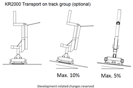
 How to park the Krupinski KR2000 in storm protection position. Image: H-G Kessel
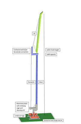
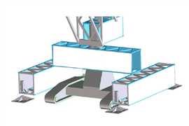
The new Krupinski KR2000A design study proposes 140 tonnes capacity and a 183 metre under hook height. When going beyond a 100 metre free standing tower this bottom slewing luffer has a load-torque-balancing tensioner to the machinery deck. It provides additional stability for the tower and allows more free-standing height without adding to the square size of the tower.
Additional benefits are that the centre of gravity is lower as the ballast and machinery platform with the hoisting and luffing winch and the climbing units are all installed at the crane’s base. Unlike those old luffers or the now common large top slewing types, Krupinski’s design is containerised for transport.
Nearly all the structural parts of the Krupinski crane are ISO-40’ or ISO-20’ container-sized modules or will fit inside those standard containers. Total transport weight will be less than 600 tonnes and individual component weights will not exceed 25 tonnes. The whole crane is designed to be transported in 24 standard container loads.
 A stiff and compact mast system allows economical free standing capacity on the Kitagawa. Image: H-G Kessel
On the move
To transport comparable luffing jib top slewing Chinese cranes that follow the original Krøll and Favelle Favco rope luffer designs requires much more oversized load transport.
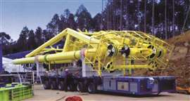
 Transport for the Kitagawa JCW1250 base, including the mast climbing system. Image: H-G Kessel
Examples are the width and height of the jib sections, plus the massive slewing ring section and the larger dimension tower segments. Often the crane’s components are more than 3 metres wide and 3 metres tall which means higher permits and more expensive low bed trailers.
In its studies Krupinski indicates a reduction in transport costs of more than three times for road transport under the restrictive North American and European laws. In addition, the size of assist crane is dramatically reduced by the initial rigging procedure thanks to the bottom slewing design.
 Overview of the Krupinski KR2000. Image: H-G Kessel
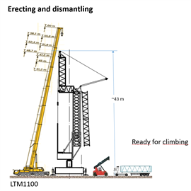
Lifting height for the larger components is much less than with traditional European style top slewing climbing tower cranes. Krupinski expects a 120 tonne capacity telescopic boom crane to be sufficient for the basic rigging procedure. For climbing, to raise the height of the crane, just a reach stacker is needed.
A typical tower crane for this application takes a week or two for rigging. Krupinski claims it will be able to install the KR2000A in two or three days. In addition, investment costs are said to be about half of the standard top slewing climbing tower crane in the same capacity range.
Getting it up
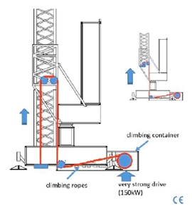
Climbing the crane with an innovative climbing rope system connected to a powerful 150 kW drive in a climbing container on the ground will improve the safety of the climbing procedure. Climbing time for each 11 metre tower section is expected to be around 10 minutes. An hydraulically supported bolting and unbolting mechanism helps speed up rigging.
In addition to economical transport and fast set up time, the crane’s wind resistance is another issue in this wind energy application. In service Krupinski claims a maximum allowable wind speed of 55 km/h. In an out of service position, with a folded down boom, 160 km/h is the maximum. With the crane climbed down to a 77 metre overall height it can withstand wind of more than 200 km/h.
 Erecting the Krupinski KR2000 using a 120 tonne mobile crane. Image: H-G Kessel
A similarly safe crane position for a free-standing tower crane design can only be found on the Japanese cranes when climbing down alongside their own tower.
 Krupinski KR2000 mast installation and jib extension using a reach stacker. Image: H-G Kessel
Energy saving
Thanks to their permanent magnet drives Krupinski cranes save up to 40 per cent on energy costs. A containerised 500 kVA power generator allows for the independent use of the crane.
 The Krupinski KR2000’s mast jacking system. Image: H-G Kessel
To reduce mobilisation time between turbine installation sites a crawler base, similar to the CC 3800 650 tonne capacity crawler crane carrier, is proposed by Krupinski to move under the portal base of the partly rigged crane. The manufacturer estimates the crawler carrier will reduce relocation time of the tower crane from one site to the next by at least two days.
 Krupinski’s crawler base design for its KR2000. Image: H-G Kessel
In addition, one crawler carrier could be used for several KR2000A cranes on the same wind farm. Remote operation is also possible. It has a programmable PLC system allowing horizontal load movements with the luffing jib similar to that of a hammerhead crane with horizontal jibs. Wind and load influences are recognised and suppressed, with the control automatically adjusting the torque of the slewing drive based on the position of the boom, thanks to a sophisticated frequency converter controlled slewing drive.
 Overview of the Kitagawa JCW1250. Image: H-G Kessel
 Crawler mounted transport for the Krupinski KR2000. Image: H-G Kessel
STAY CONNECTED


Receive the information you need when you need it through our world-leading magazines, newsletters and daily briefings.
CONNECT WITH THE TEAM